
Sub-Inch Per-Pixel Resolution Geospecific Aerial Imagery and Terrain for Real-Time Visualization
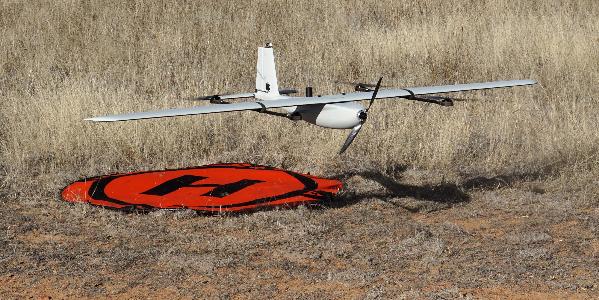
MVRsimulation's small UAS, developed by SRP Aero. (Photo courtesy of SRP Aero.)
MVRsimulation has established a low-cost UAV data collection and processing workflow which yields ultra- high-resolution real-time 3D terrain. The terrain is comprised of geographically specific 2 cm per-pixel resolution imagery. Using MVRsimulation’s Terrain Tools for Esri® ArcGIS® to combine high-resolution imagery of an area of interest with accurate satellite elevation data or other digital elevation models (DEMs) results in a realistic geospecific synthetic environment rendered in MVRsimulation’s Virtual Reality Scene Generator (VRSG).
The workflow includes content creation using Autodesk 3ds Max and other modeling tools to create custom 3D models of any or all of the surrounding area elements, based upon aerial and/or ground-level photographs. Content can be relevant and specific to various kinds of simulation training, such as military mission exercises, law enforcement, or emergency/disaster response.
MVRsimulation's small UAV for imagery data collection, is a low profile, lightweight, vertical take-off and landing (VTOL) aircraft, built for autonomous aerial surveying. The purpose of the UAV is to take high-resolution still-frame images that are then orthorectified and can be used for building 3D terrain for rendering in VRSG.
The UAV, built by SRP Aero, is designed to fly at low altitudes in order to capture images at sub-inch resolution.
The images on this webpage illustrate the process of collecting and processing the imagery and then using the imagery for building terrain and 3D content. The examples come from recent deliveries to customers and a sample test dataset built from imagery of an arid rural area that SRP Aero provided to MVRsimulation.
MVRsimulation VRSG real-time scene of 2 cm per-pixel terrain of a range at the Fallon Range Training Complex.
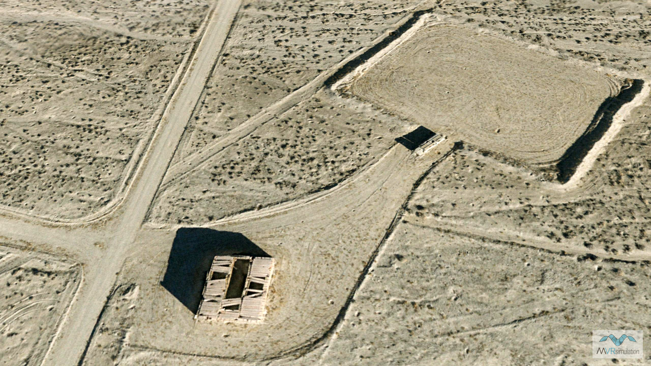
As part of a simulation technology upgrade to the training dome and desktop systems, MVRsimulation delivered to the Naval Aviation Warfighting Development Center (NAWDC) at Naval Air Station (NAS) Fallon, NV, high-resolution geospecific terrain of two target ranges on the Fallon Range Training Complex (FRTC) used for field training in the facility's JTAC qualification course. The 2 cm per pixel imagery of the B-17 and B-19 ranges was captured by MVRsimulation's small UAV over the course of 9 days. The UAV was flown by SRP Aero in military controlled airspace. With the UAV’s 24 MP and 36 MP cameras and NED 10 meter elevation data, MVRsimulation compiled full-resolution (2 cm) terrain tiles of the ranges with MVRsimulation Terrain Tools for Esri ArcGIS. The total area of coverage of this terrain data set is 65.81 sq km.
At 2 cm resolution, details such as helicopter landing areas, vehicle targets, and small craters left from exploded ordnance are visible on the terrain and bullet holes are visible on targets. (Underlying the high-resolution 3D terrain of the two ranges is MVRsimulation's CONUS ++ terrain, which was built with 1 meter per-pixel terrain imagery and DTED-1 elevation data.)
This next image is from another project, where 2 cm imagery was captured at Yuma Proving Ground by MVRsimulation's small UAV, and the resulting imagery was used to build 2 cm terrain.
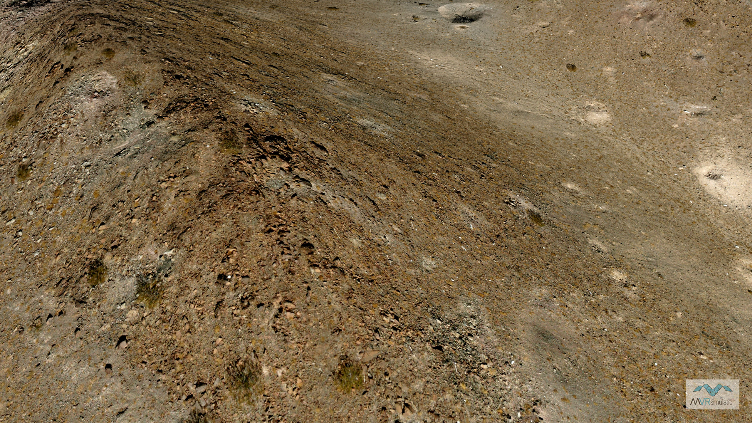
MVRsimulation VRSG real-time scene of 2 cm per-pixel terrain of the Prospect Square area Yuma Proving Ground.
The following VRSG screenshot shows the main road of terrain of an early imagery-collection testing area built with 2.5 cm imagery. The imagery of this road was captured with a small rotary-wing UAV at a higher, 5 mm, resolution. As a validation of the technology, the screenshot shows how well the 5 mm resolution road blends into the rest of the 2.5 cm terrain at the shoulder of the road.
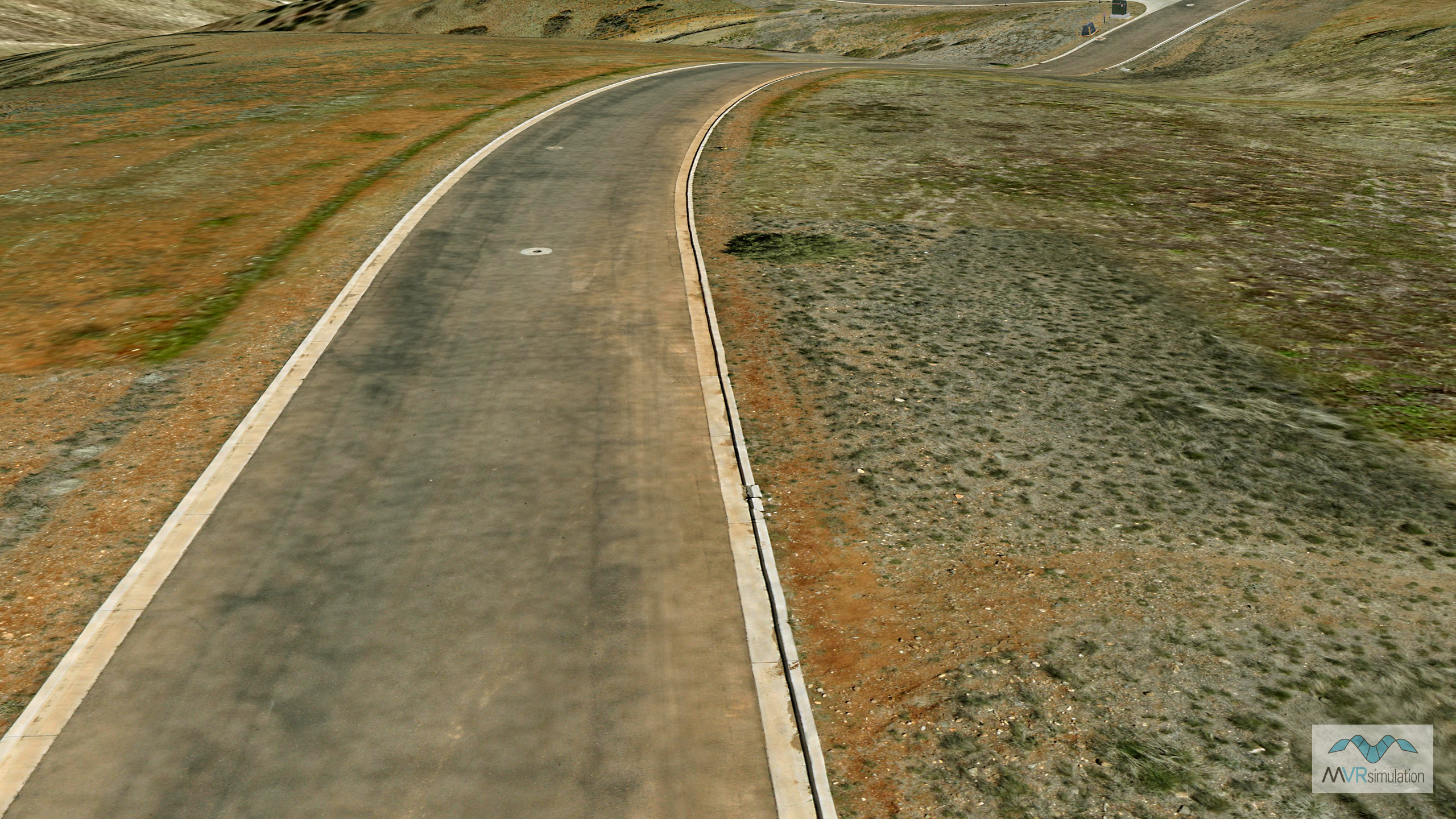
MVRsimulation VRSG real-time scene of 2.5 cm terrain featuring a road built with imagery captured with a small rotary-wing UAV at a higher, 5 mm, resolution.
Aircraft specification
Click here for the latest technical specs of MVRsimulation's small UAV, which is the Lynx VTOL, developed by SRP Aero.
Launching the aircraft
Lynx VTOL takes off with the touch of a button. Four dedicated motors lift the aircraft vertically to a predetermined height. Once at altitude, a single high-efficiency motor propels the aircraft forward to fly like an airplane.
Landing the aircraft
For landing, Lynx VTOL comes to a stop midair and descends vertically to its landing spot. VTOL landings are predictable and accurate to within two meters.
Payloads
A modular payload bay sits beneath the wing allowing users to fly the best cameras available. These camera options are currently offered with custom payloads supported as well.
- Sony a6000 24 MP RGB APS-C sensor
- MicaSense RedEdge-MX multispectral 5 band (RGB, RE, NIR)
Watch the video below to see the take-off and landing of the aircraft.
Preparing to collect the raw imagery data
Data collection for an area up to 4.5 sq km takes approximately 2 hours, yielding about 4000 raw images. Weather (wind), desired image overlap, and desired resolution (altitude) can cause this duration to increase or decrease. The best time to fly the aircraft for imagery collection is solar noon. With a low winter sun that timeframe is approximately 11 AM to 3 PM.
Ground control station and platform software
Interaction with the aircraft is via SRP Aero's GCS software (Swift GCS), which runs on the Windows and Linux operating systems. The GCS features a simple touch-screen interface that is ideally suited for field tablets, and requires minimal computing hardware to run. The GCS guides you through the flying process via the built-in checklist and preflight steps. Survey planning is fully integrated with controls and drag-and-drop waypoints.
The GCS receives live updates from the aircraft through the telemetry radio. Through the GCS you can change flight modes or modifying an existing flight path while the aircraft is in flight.
The on-board ArduPilot, an open-source autopilot, autonomously controls the aircraft in flight.
Setup
The aircraft features a clip-on tail and removable three-piece wing for easy transport and rapid assembly. The entire system packs down into one airline checkable hard case that fits within the trunk of an automobile.
It takes approximately 10 minutes to set up and launch the aircraft after removing its components from its waterproof ruggedized transport case and initializing the GCS software on the Windows or Linux notebook computer or tablet.
Note: The flight batteries are non-dangerous goods (DG) and can be shipped worldwide.
PROCESSING THE IMAGERY
Raw aerial images require geometric correction, or orthorectification, with GIS tools to remove distortions, enforce a uniform scale of distances, and improve the positional accuracy (using the ground control points) so that they depict an accurate representation and correspond to real-world coordinate systems.
MVRsimulation’s aerial imagery provides high-resolution geo-referenced orthomosiacs. During orthorectification, the high-resolution images collected by UAV are registered with real-world coordinates and overlaid onto DEMs to simulate the 3D terrain environment.
The orthorectification process of an imagery data collection can take a couple of days to a week, assuming the orthorectification results are satisfactory. During this process the images are mosaiced (assembled) into a uniform tiling scheme. After the imagery has been orthorectified, it is ready to be used to build 3D terrain.
Building 3D terrain with the orthorectified imagery
With MVRsimulation Terrain Tools for ArcGIS, you can readily use the high-resolution orthorectified imagery for building terrain tiles in MVRsimulation's round-earth VRSG terrain format.
The orthorectified images, together with elevation data of the photographed region become source data inputs for MVRsimulation Terrain Tools to compile the terrain tiles. The resulting terrain tiles can be rendered in VRSG at 60 Hz.
With imagery at this resolution, you can create a physics-based IR profile of the terrain with a high degree of realism. Using the IR Setup utility that is delivered with VRSG, you would describe the sensor’s spectral response within its waveband of interest, train the material classifier, and specify the environmental characteristics that influence the appearance of the IR scene. The material classification process automatically generates material attribution from visual spectrum colors. This means that the higher the resolution of the visual database, the more accurate the IR profile.
CREATING 3D content from ground-level photographs
Aerial imagery can be correlated with ground-level photography in order to make 3D models of particular features of interest. Perspectiveless photographs are taken with at least a 16-megapixel camera of the feature of interest, ideally in overcast conditions. One set of photographs are taken to give an overall reference of the subject and then key reference features of the building such as doors, windows and so on are photographed by zooming in to focus on the key feature. Again, perspectiveless photographs are taken such that they can be used for creating textures on the 3D model.
While creating 3D building models from aerial photography or satellite imagery is common, such models are generally not useful for ground-level orientation as they lack resolution in both geometry and textures. Typically a heterogeneous terrain model is made from overhead imagery, 3D models are made from imagery for intermediate resolution, and finally 3D content is made from ground-level photographs to provide the highest level of detail.
Ordering aerial imagery or terrain
Aerial imagery collected by the UAV can be ordered directly from MVRsimulation by specifying the area of interest (AOI), such as an airfield, or a training area.
An aerial imagery order consists of:
- Raw collected photographic imagery data at 2 cm resolution.
- Orthorectified GEOTIFF imagery (processed by MVRsimulation) to be used with your Terrain Tools for ArcGIS software license.
- Dataset of terrain tiles in round-earth VRSG terrain format at 2 cm resolution to be used with your VRSG software license.
Aerial imagery orders must be for an area of a minimum of 20 sq. km. Access to the area of interest for aerial photography must be in accordance with FAA regulations. Customers will be responsible for obtaining the necessary authorization and certified access to operate a restricted airspace of interest for aerial photography.
Customers have unlimited unrestricted use rights to the imagery. MVRsimulation retains the right to use the collected data and resulting terrain tiles and to redistribute the terrain tiles (typically as part of a larger set of terrain tiles of a region).
COMPARISON OF 2 CM AND 5 MM DRONE IMAGES
The following images were recently captured by MVRsimulation's small UAVs at Rick Husband Amarillo International Airport (KAMA), TX. The 2 cm per-pixel images were captured by our hybrid VTOL UAV; the 5mm per-pixel images of the same location were captured were captured by our quadcopter UAV.
The UAVs were built by SRP for autonomous aerial surveying at low altitudes. SRP also flew the UAVs at Amarillo airport.
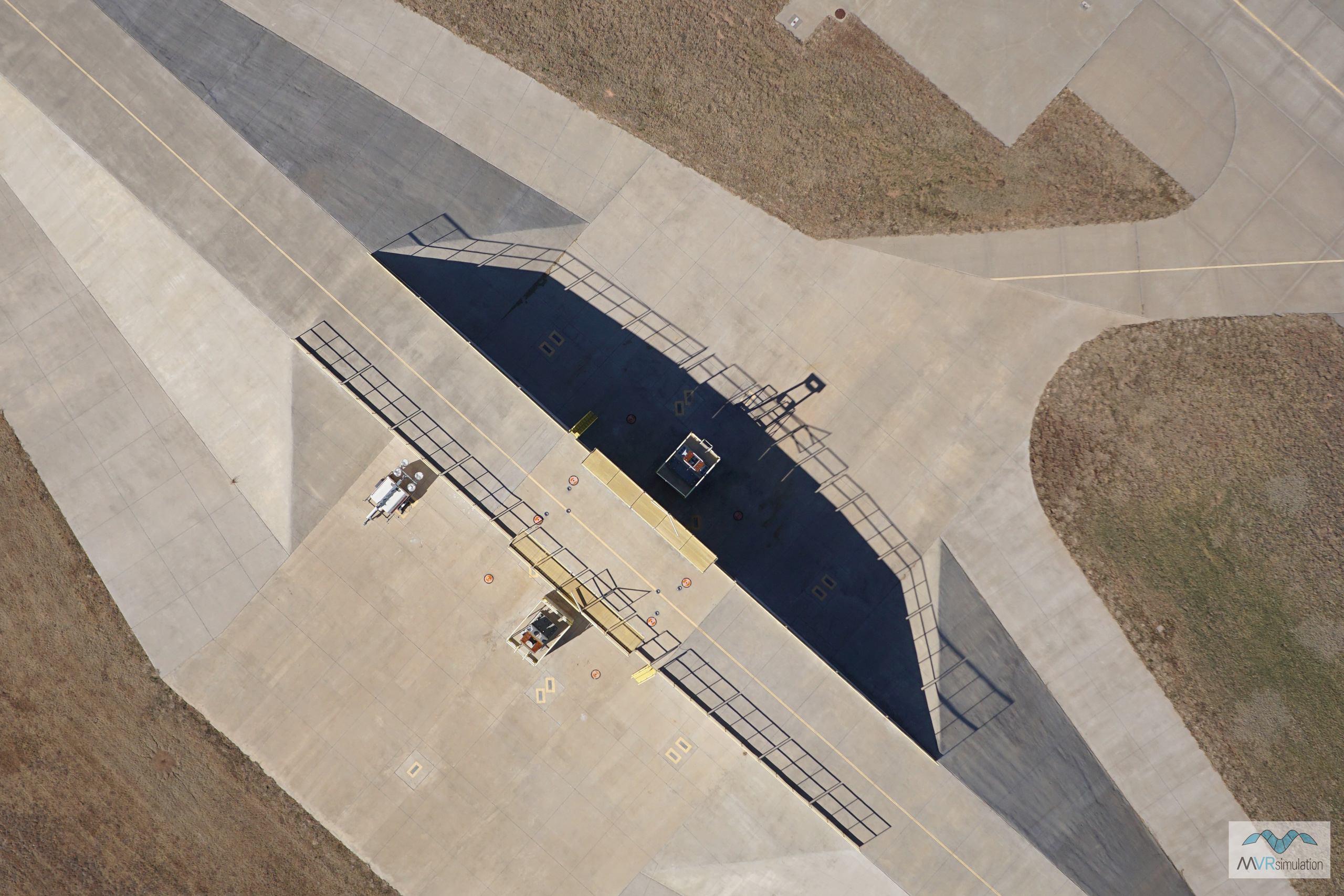
2 cm imagery of runstand area. Click here to see the original 4000 x 6000 imagery.
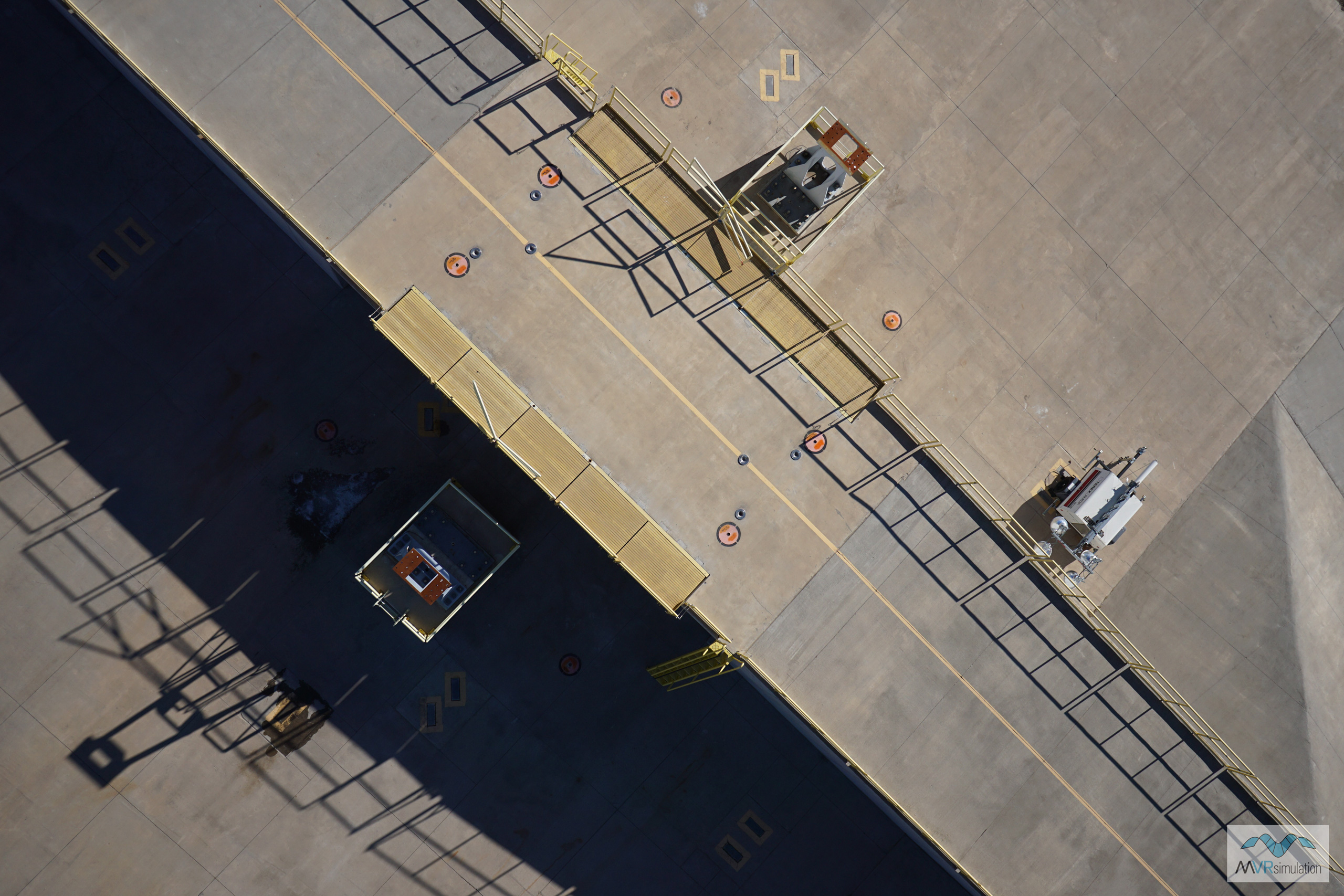
5 mm imagery of the same run-up area. Click here to see the original 6000 x 4000 imagery.
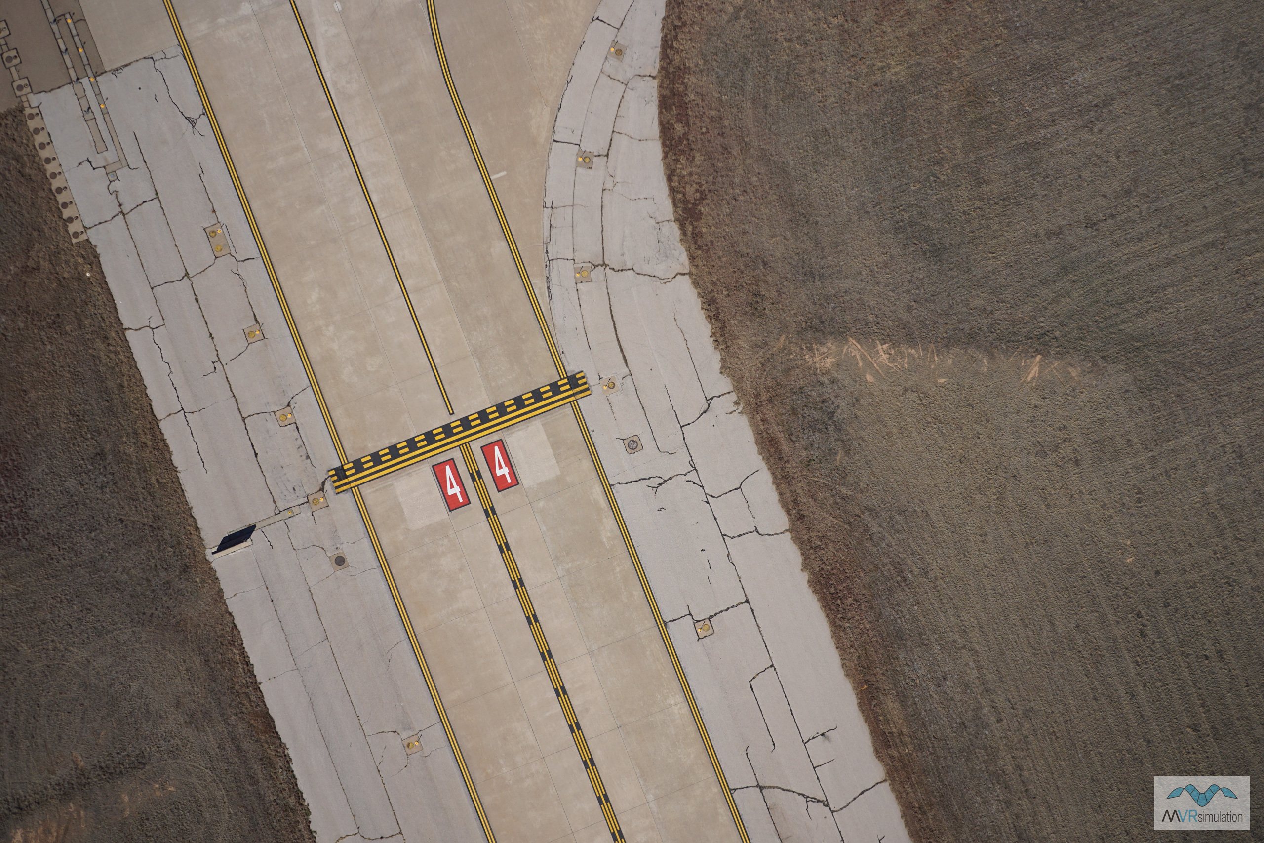
2 cm imagery of a taxiway. Click here to see the original 6000 x 4000 imagery.
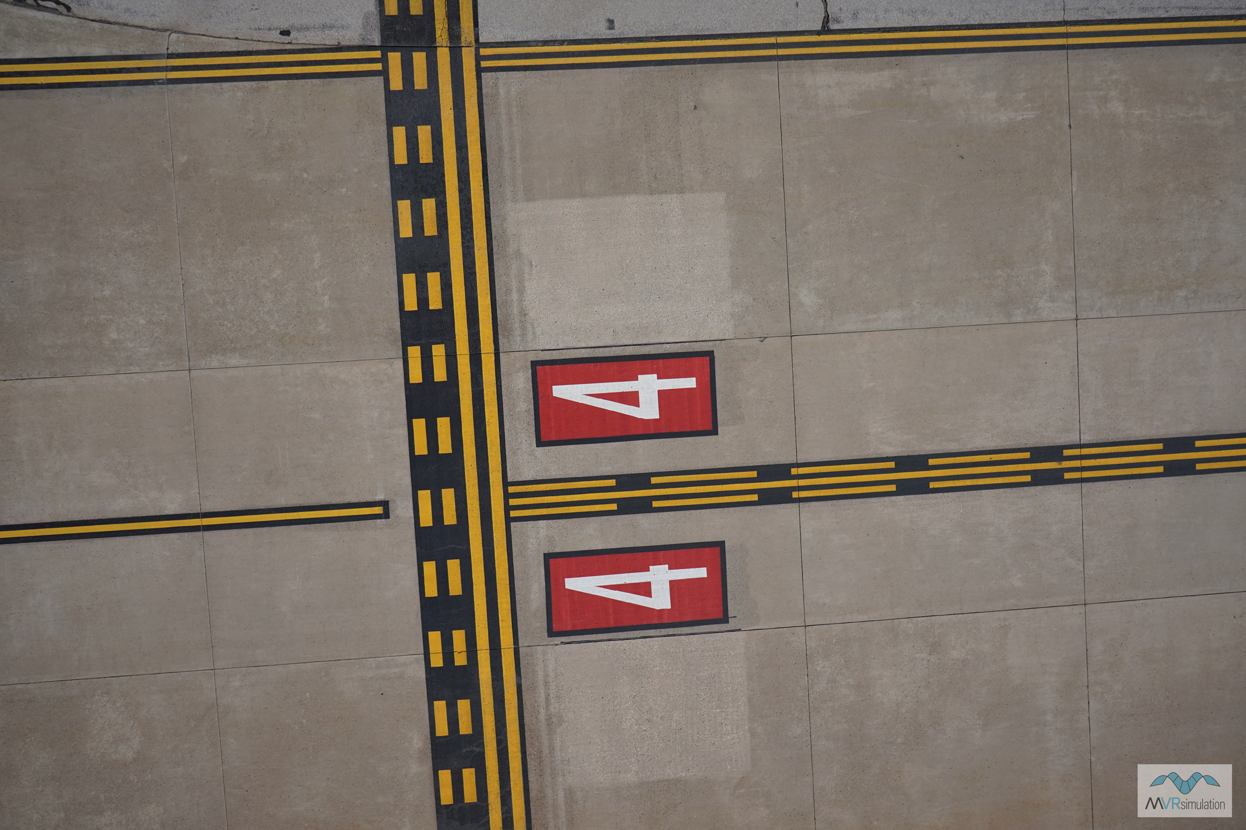
5 mm imagery of the same taxiway. Click here to see the original 6000 x 4000 imagery.
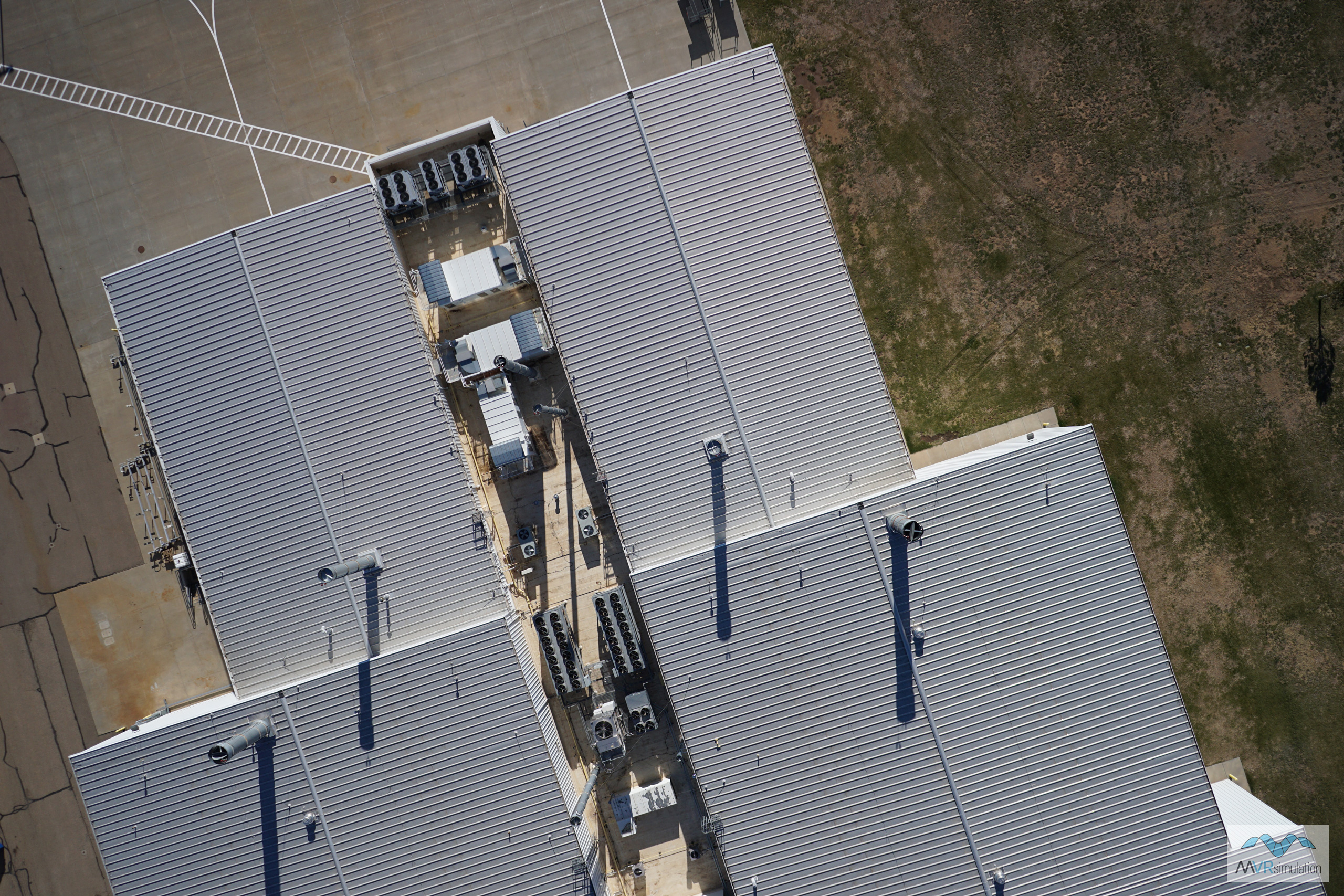
2 cm imagery of a rooftop. Click here to see the original 6000 x 4000 imagery.
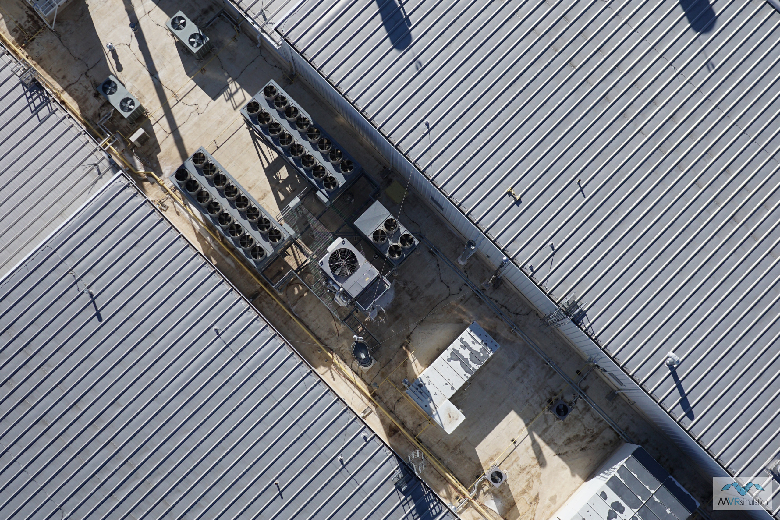
5 mm imagery of the same rooftop. Click here to see the original 4000 x 6000 imagery.